
The weird and wonderful worlds of combat robotics has always been something that I have held a strong affinity for. With Robot Wars at the height of its popularity while I was a child, it is perhaps only natural that I grew up dreaming of one day building my own destructive fighting machine.
Creating a machine capable of appearing on shows like Robot Wars and Battlebots involves a lot of skill, time and money (anywhere between £3500-£50,000 and more).
Instead of focusing on large, incredibly expensive projects, we have looked for ways to recreate this duelling robot obsession on a smaller, far more wallet friendly scale. Planet Codebot previously tested and reviewed two DIY Battle Robot Kits, from Science Salad. These wooden robot kits are a great first step for building and playing .
Today, we will explore how to go one step further and look into creating a fully functional, 3D printed robot.


Choose Your Weight Class
Fighting robots fall into different categories based on weight and size, much like boxing, martial arts and MMA competitions. Each category will have its own weight limit, power limit and rules on safety equipment. Some categories will also have size limits too. The full rules can be found on the Fighting Robots Association website.
Weight classes different slightly depending on which country you are in. The main weight classes which fight in the UK are:
- Heavyweight: 110kg
- Middleweight: 55Kg
- Lightweight: 30Kg
- Featherweight: 13.6Kg
- Beetleweight: 1.5kg
- Antweight: 150g
- Fleaweight: 75g
- Nanoweight: 25g

Parts, Materials and Tools
Any combat robot will require several parts to work, such as a battery, motors, speed controllers and wheels. For this project, I have chosen to use this Beetleweight Drive Kit from Bristol Bot Builders. This kit contains virtually all the components needed to create a working robot. BBB provide good quality parts and perhaps most importantly, the pricing is always very reasonable.
Bristol Bot Builders have produced an excellent step by step guide, as well as wiring diagrams for this build. These are excellent tools for any first time builder.
To power and control the robot, a transmitter and battery will also be required. There are many options available on the market. I have opted for a Turnigy i6 and a 3S Lipo battery. Make sure your motors and controllers are compatible with the battery you choose. If the voltage is too low, the robot wont run; Too high and you risk burning out the motors completely.
The body (chassis) on my robot is 3D printed from PLA filament. PLA isnt the strongest material to print with, so I wouldn’t recommend it for real battles. It is, however, cheap and quick to work with. This makes it perfect for testing out various designs before settling on a final one.
Obviously, this will require the use of a 3D printer. Entry level printers start from as low as £100. However, if you don’t own one (or know someone that does), it is possible to visit a local Makerspace and use theirs instead.
Designing The Body
As the chassis is being 3D printed, this provides an excellent opportunity to create our own design. Combat robots often come in weird, wacky and wonderful shapes and designs, so let your imagination run wild.
I have used Tinkercad to create the 3D file for printing. Tinkercad is an incredibly simple online CAD software, which is free to use. By combining simple geometric shapes, it is possible to create complex and detailed designs.


The STL files for this design can be downloaded for free via Planet Codebot’s Google Drive folder, which is linked below. Alternately, you can copy the file to edit yourself here.
3d Printed Combat Robot – Google Drive
Assembling The Electronics
Building the circuit for your robot is reasonably straight forward. It will however require some soldering. Like any skill, soldering takes practice. It can at times be a frustrating task and is arguably the biggest barrier to completion for many projects. It doesn’t have to be this way though. By following a few small tips, you can avoid the biggest soldering pitfalls.
- Get a good quality solder with a rosin flux core. Flux helps remove and prevent oxidisation of the metal while soldering. Solder wire with a flux core (like this product) can really help to really help to remove the frustration from soldering.
- Pick the right tip and get the heat right. Soldering irons are generally inexpensive and often come with several attachments and tips. Pick a tip that is suitable for the job you are completing. Wider tips allow for more heat to pass, while smaller tips help to avoid damage to sensitive components in the surrounding area.
- Invest in a good helping hand. Trying to hold a soldering iron, solder and two components together at the same time is not easy. A reliable helping hand can provide a stable platform for you to work off of, and keeps your hands away from the hot end of the iron. This example from Amazon, while pricier than others, has proved an outstanding purchase.
- Wear the proper safety equipment. When soldering, goggles or glasses should be considered essential.
Click the video play button to see a walkthrough of the circuit in action.
Test Drive
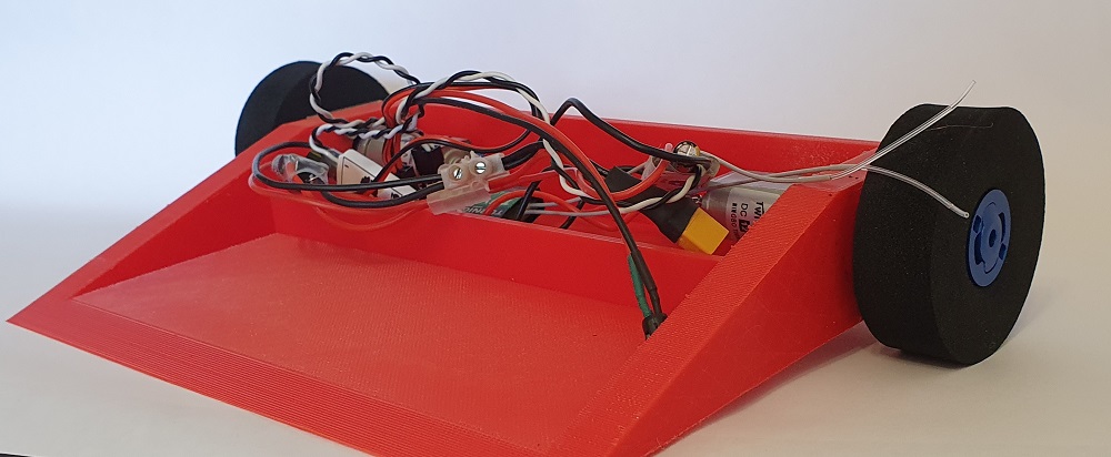
Now that the body has been printed and the circuitry has been completed, it is time to test drive the robot.
The two motors are currently independently controlled by separate ESCs. It is necessary to ‘mix’ the throttle on the transmitter, so that the signal gets adjusted to control both motors simultaneously. I haven’t finished this yet on my wicked wedge bot, so the driving is quite erratic.
As the robot is (almost) fully functional, it is time to improve upon the design and make it competitive. I intend on designing a top for the robot, so the components don’t spill out when moving around.
